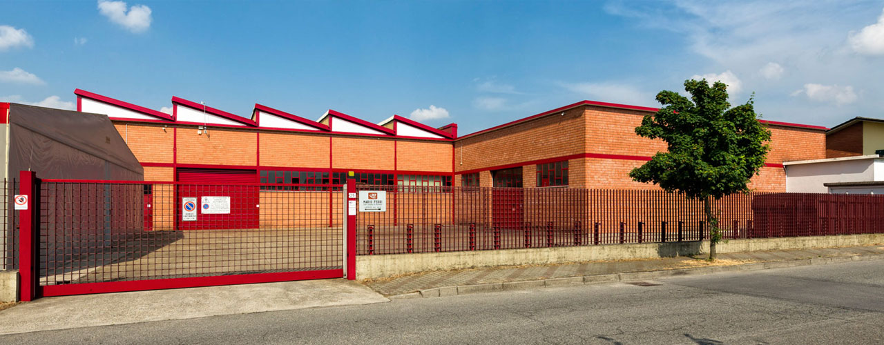
Mario Ferri Srl headquarters in Via Miglioli 2 a Castelleone (CR)

- Category: Uncategorised
- Hits: 5408
Mario Ferri puts forward a new idea of design. mechanics. technology.
Mario Ferri has been specializing exclusively in the manufacturing of universal joints for more than fifty years. Thanks to this specialization, its universal joints have always achieved the highest levels of precision and reliability.

The constant technological upgrading of production equipment, together with continuous attention to the increasingly sophisticated demands of an evolving market, has enabled Mario Ferri to develop a comprehensive range of universal joints capable of meeting every customer's requirements.
For any specific universal joint transmission requirement, Mario Ferri is at your disposal to identify the most suitable technical and commercial solution.
- Category: Uncategorised
- Hits: 2725
SELECTION CRITERIA
When a single joint is connected to two shafts forming an angle, with the driving shaft rotating at a constant speed, a periodic variation occurs in the speed of the driven shaft, resulting in exactly four fluctuations per revolution.
The difference between the maximum and the minimum speed of the driven shaft depends on the angle formed by the two shafts. The difference increases as the angle α increases.
To have a homokinetic transmission, you have to fit either two opposite single joints (paying attention that the two central yokes lie on the same plane and the angles are equal) or a double joint.
The irregularity generated by the first joint is compensated by the second. The overall length can be further reduced by using a double joint. In other words, the double joint is to be considered as the shortest homokinetic transmission.
For low speed applications (max 1000 rpm) joints with plain bearings (sleeve bearings) are recommended (types S, G/GB).
They are capable of withstanding shock loads, irregular operating conditions and relatively high torque values.
The working angles must be kept between 500 and 1000 rpm.
For high rotational speeds, relatively low torques, motion reversals or wide angles, joints with needle roller bearings (type H) are to be preferred.
They can reach 4000rpm always relating to the angle α.
HOW TO READ THE DIAGRAMS
The joint capacity to transmit a regular torque at a constant load with no shocks, for a more or less long period, mainly depends on the number of revolutions per minute and the inclination angle α of the two axes.
The diagrams below have been developed according to this criterion.
Each curve corresponds to the joint size (outside diameter ØD) and represents the torque that the joint can transmit according to operating speed and working angle α.
The diagrams can be directly read if angle (α) is 10°. For larger angles, transmissible torque is reduced, therefore these are to be corrected using the correction values (F) relating to the angle shown in the table.
IMPORTANT: The values shown in the diagrams are for guidance only and are referred to the single joints only. When choosing a double joint, you have to consider that this one can transmit a torque about 10% lower than the same sized single joints. Each application has its own particular motion characteristics, such as: shock loads, motion reversals, connected masses, kind of starting, presence of elastic joints, stops and starts, etc, that have to be considered by the user when chosing the joint.
Diagram for JOINTS S-G

Example:
- Power: 0.65 kW
- R.P.M.: 230
- With working angle α 10° Value F=1 we get point P. Torque = 27 Nm corresponding to joint size ØD = 25/26 mm. = Types 04S, 04G, 1GB
- With working angle α 30° Value F=0.45 (kW 0.65 / 0.45 = 1.44 kW) we get point P1 Torque = 60 Nm corresponding to joint size ØD = 32 mm. = Mod. 1S, 1G, 3GB.
Consider that: Torque (Nm) = 9550 × (Power (kW)) / R.P.M.
Torque (Nm) = 7020 × (Power (HP)) / R.P.M.
 Download PDF
Diagram for JOINTS H

Example:
- Power: 5.5 kW
- R.P.M.: 2300
- With working angle α 10° Value F=1 we get point P Torque = 23 Nm corresponding to joint size ØD = 28/29 mm. = Types 05H
- With working angle α 25° Value F=0.70 (kW 5.5 / 0.70 = 7.85 kW) we get point P1 Torque = 33 Nm corresponding to joint size ØD = 32 mm. = Types 1H, 3HB.
Consider that: Torque (Nm) = 9550 × (Power (kW)) / R.P.M.
Torque (Nm) = 7020 × (Power (HP)) / R.P.M.
Instructions for Correct Installation

a. To obtain a uniform rotary motion always use either two opposite single joints or one double joint. The pillow blocks are to be positioned as close as possible to the joints (see PICTURES 1 and 2).

b. When using two opposite single jointsensure correct alignment of the inside yokes. In telescopic transmissions also pay attention than the alignment marks are correctly matched (see PICTURES 3 (CORRECT), PICTURE 4 (WRONG)).
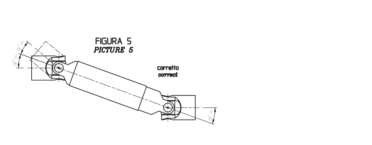
c. The operating angles α of the joints must be equal (see PICTURE 5).
© Copyright 2024. All Rights Reserved.